Greg Cordover
Thoughts & projects
Converting American Lighting Neon LED Strips To WLED
Costco recently had the American Lighting Color Changing Neon Flex Light LED strips on sale for $15 each1. Given that you can’t find a bare strip of addressable LEDs on Amazon for that price, a set of that cost including diffusion, power supply, and remote was too good to be true.
After getting a chance to look over the strips in person, I was pleasantly surprised by how good of a value they were. Unlike most strips which run 5 volts down the whole length for power, these use 24 volts. This can prevent a noticeable shift in colors and brightness on longer strips. However, the LEDs were grouped into segments of six, and couldn’t be individually addressed. This likely wouldn’t affect plans for mood lighting, but it is something to keep in mind for specific projects.
The biggest disappointment of these LED strips is how basic the included controller was. It has only a few color choices and animated effects, and lacks essential controls such as brightness. It uses the limited number of buttons for presets such as the Fourth of July, Halloween, and Christmas. And my least favorite part was that it uses infrared, requiring line of sight and making it more difficult to automate with my preferred smart home software, Home Assistant.
Technical Analysis
While I was curious how they worked after finding the product listing, the controller’s shortcomings motivated me to properly investigate how they were wired so I could determine if it was possible to make them smarter.
My first step was identifying how the strips were wired together. Looking at the connector revealed three pins. These were quickly identified using a multimeter as ground, +24V, and data. This was initially a concern, as common LED strips use 5V and this higher voltage could suggest they were using a non-standard protocol.
Next, I connected it to a $12 logic analzyer I picked up on Amazon. These devices are fantastically useful for debugging signals, and cheap enough you don’t have to worry about their misuse. In combination with software like PulseView, one can very easily identify and decode digital signals.

Luckily, the signal was identified as the WS281x protocol, the same strategy of data transmission as most addressable LED strips you can buy!
Knowing the signal doesn’t say anything about the voltage characteristics, which is very important for determining what would be required to connected them to a different controller.
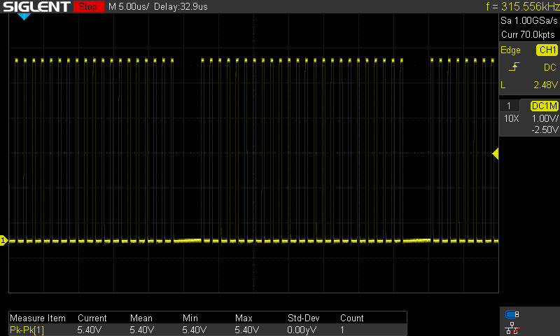
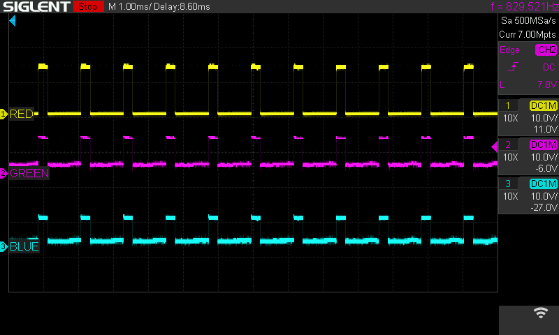
A quick probe from an oscilliscope revealed the controller used 5.4 volt signaling.
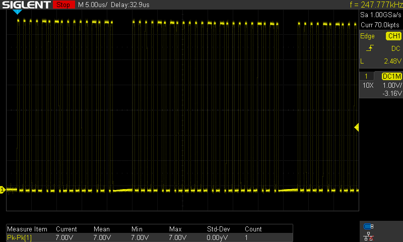
These strips are chainable, and probing the output shows an even higher voltage around 7 volts. This told me that these strips are tolerant of a wide range of voltages, hopefully indicating good compatibility with custom controllers.
While investigating the voltage levels, I found one strip that didn’t seem to allow chaining other strips to the end. There were a few people in the reviews mentioning that chaining didn’t work for them, even after making sure to enable two strips with the remote.
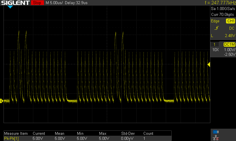
Unlike the previous signals, this output did not have clearly defined 1s and 0s. Something must have gone wrong when it was being manufactured. This could be a common defect and would explain those reviews. I didn’t want to disassemble it to find something difficult to repair, so I returned it.
I also took a few other measurements about the LEDs while hooked up to the oscilliscope. In order to get some more data, I cut open the end of one of the strips to access the controller for a segment.
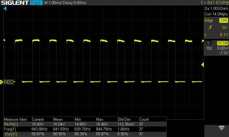
These LEDs seem to have a PWM frequency of around 840Hz, putting them solidly in the mid-tier range. They shouldn’t have noticeable flicker to people, but it might be visible in slow motion video.
Physical Construction
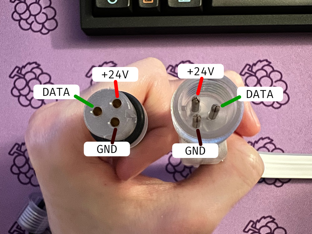
The connectors have three pins and are water resistant.

They are conventional LED strips, packaged into a molded enclosure. As expected, there are six LEDs and one controller per segment, along with a few resistors and capacitors.
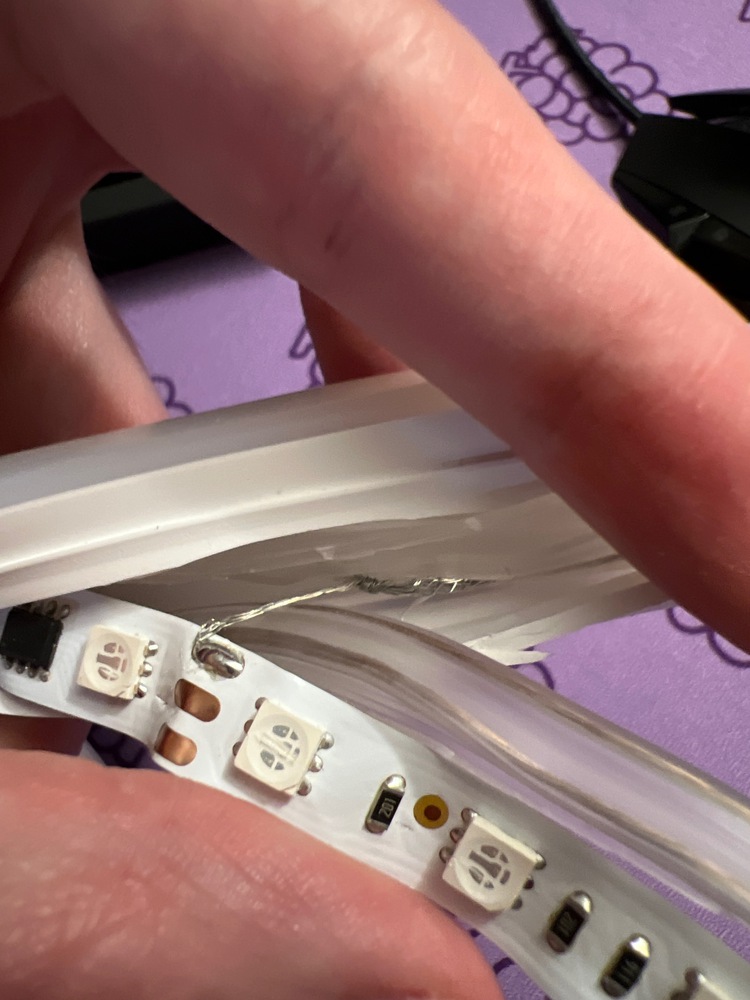
The most concerning thing about their construction was that wires soldered to the internal strip were only wrapped around the main wiring running through the casing. This could explain why a number of strips had poor connections for data.
Finding a DIY Controller
In my opinion, the best solution for controlling LEDs these days is the WLED project. It allows you to turn an ESP8266 or ESP32 module into a WiFi-enabled LED controller filled with all kinds of features, and most importantly for me, integrates seamlessly with Home Assistant.
With a controller in mind, I needed to decide how to connect everything together. We know from earlier that these strips are confirmed to work with 5.4 to 7 volt signals. The ESP modules can output 3.3 volts. This mismatch could be a problem. We don’t know the acceptable input range for these strips.
Thankfully, electronics expecting a higher voltage don’t harm a device outputting a lower voltage. I tried connecting a module directly to the strips with mixed results. It sometimes worked on some of the strips. I wanted to avoid this kind of unreliability, so a solution had to be discovered.
While many ESP modules are part of development boards featuring voltage regulators, I wanted to use an ESP-01 module because of their reduced size. This allowed me to fix the issue in an untraditional and potentially risky way, by turning up the voltage supplied directly to the ESP8266 on board.
In order to not need a separate power supply, I attached a small buck converter to drop the voltage from 24V to the 3.3V the ESP requires. These converters can be set to any voltage using a potentiometer. I very slowly turned up the voltage until all of the LED strips I had started working reliably, which ended up being around 3.7V. While out of specified range for these chips, it seems to be working reliably without generating more heat than usual.
I believe the more correct solution would be to integrate an ESP board with a 5V regulator and use a level shifter to convert between the ESP’s 3.3V output and the higher voltage required for the strips, but this would be considerably more bulky without creating a custom circuit board with these features.
Instructions To Build Your Own
- Purchase all of the needed parts. You’ll need a strip or two of LEDs, an ESP module, buck converter, and some wire and tools to solder all of the parts together. If you don’t want to push your luck, you’ll also need a level shifter to convert 3.3V to 5V and an ESP module with a 5V regulator.
- Remove the existing controller. The casing can easily be popped open, revealing a basic circuit board. Desolder it to prepare for the new controller.
- Identify and label the wires. The positive and negative wires sometimes flip color between the input and output of the controller. Make sure you correctly identify each one with a multimeter.
- Connect the +24V wire to both the LED strip and the positive input of the buck converter. Then connect the ground wire to the strip and negative input.
- If using an adjustable buck converter, plug it in and use a voltmeter to set the output voltage. When using a bare ESP module, set it to 3.3V. If using a board with a regulator, set it to 5V. When set, unplug everything.
- If using a level shifter, connect the 5V output of the ESP module’s regulator and ground to the level shifter. Identify which pin you are going to use as the output from the ESP module and connect it to an input on the level shifter.
- Connect the output from the ESP module or level shifter to the signal input of the LEDs.
- Everything should be ready to go now! Give it a test.
Closing Thoughts
These LED strips provide a reasonable value off the shelf and an incredible value if you’re willing to tinker with them. The included controller is lacking for more than the most basic of use but can be replaced by a far more powerful one with relatively little trouble.
If you’re in the market for cheap LED strips where the strip itself is visible or they’ll be put outdoors, these could be a great choice.
As of August 2022, they seem to be readily available for $20 but are marked in-store as an item that will not be restocked. ↩︎